Namespace ABB.Robotics.RobotStudio.Stations
Classes
Annotation
Represents a persisted graphical annotation displayed in the 3D graphics.
AnnotationCollection
Represents a collection of Annotation objects
ArrowAnnotation
Represents an arrow annotation displayed in the 3D graphics.
Asset
An asset is a piece of binary content that is embedded in a Smart Component. RobotStudio uses assets to store string resources and the Code Behind assembly. Any kind of binary data that is needed by the smart component can be added as an asset.
AssetCollection
Represents a collection of Assets contained by a SmartComponent or a Station.
Attachment
You can attach an object (child) to another object (parent). Attachments can be created on part level and on mechanism level. When an object has been attached to a parent, moving the parent also moves the child. One of the most common attachments is to attach a tool to a robot
AttachmentCollection
A Collection of Attachment objects.
Body
A body is typically a single 3D solid or a 2D surface, but it can also be several disjoint lumps treated as one body.
It is the highest level object in the geometric model. Several bodies can be grouped in a Part.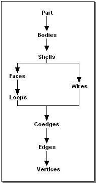
BodyCollection
A collection of Body objects.
BuiltInControllerSourceSignals
Gives access to built in data recorder signals, that represents information from the controller.
BuiltInDataRecorderSignals
Gives access to the identities of the built in data recorder signals.
BuiltInSmartComponentSourceSignals
Gives access to built in data recorder signals, that represents information from SmartComponents.
Camera
Represents a camera that can be used to control the view of a GraphicControl.
CameraCollection
A collection of Camera objects.
ClipPlane
Defines a plane that can be used to clip geometry in a GraphicControl.
ClipPlaneCollection
Represents a collection of ClipPlane objects.
Coedge
A coedge is closely related to an edge. A coedge stores its relationships with adjacent edges and
with superior owning entities. (In some contexts, the coedge may be viewed as the use of an edge
by a face or wire.) The data structures formed by these relationships (stored as pointers) and their
interpretation depend upon the nature of the owning entity.
CoedgeCollection
A collection of Coedge objects.
CollisionDetector
Provides collision detection on Collision Sets.
CollisionEventArgs
Provides data for the Collision event.
CollisionObjectCollection
A collection of GraphicComponent collision objects.
CollisionSet
Defines two groups of objects that will be tested for collision against each other.
CollisionSetCollection
A collection of CollisionSet objects.
ControllerSimulationConfiguration
Specifies the behavior of the simulation for an VirtualController.
ControllerSimulationConfigurationCollection
Represents a collection of ControllerSimulationConfiguration objects.
DrawingAnnotation
DynamicProperty
An object attached to a SmartComponent that has value, type and attributes. The property value is used to control the behavior of the SmartComponent
DynamicPropertyChangedEventArgs
Provides data for PropertyChanged and PropertyValueChanged
DynamicPropertyCollection
Represents a collection of DynamicProperties attached to a SmartComponent.
Edge
An Edge is bounded by one or more vertices, referring to one Vertex at each end. Edges are
closely related to Coedges, which allows the Edge to occur in more than one
Face, thus makes it possible to create solids.
EdgeGraph
Helper class to simplify edge traversal for a set of connected edges in a body
EvaluateTriggerEventArgs
Provides data for the EvaluateTrigger event.
EventTable
EventTableAction
EventTableActionAttach
EventTableActionCollection
EventTableActionCustom
EventTableActionDetach
EventTableActionIO
EventTableActionMechanicalPose
EventTableActionMonitor
EventTableActionMove
EventTableActionNothing
EventTableActionShow
EventTableActionTimer
EventTableEntry
EventTableEntryCollection
EventTableTrigger
EventTableTriggerCollision
EventTableTriggerCustom
EventTableTriggerIO
EventTableTriggerLogic
ExecuteActionEventArgs
Provides data for the ExecuteAction event.
Face
A face is a bounded portion of a single geometric surface, the two-dimensional analog of a body. The boundary is represented by one or more loops or edges. Each face is simply connected, implying that one can traverse from any point on the interior of the face to any other point on the interior of the face without crossing the boundary of the face. In general, it is not meaningful to distinguish exterior and interior loops of edges, though for certain surface types this may be possible and some algorithms may do so.
FaceCollection
A collection of Face objects.
Frame
Represents a simple modelling frame.
FrameCollection
Represents a collection of Frames in a Station.
GenericGraphicExportSettings
Contains common graphic export settings.
GraphicComponent
The base class of all objects in the station that represent physical objects or entities.
GraphicComponentCollection
A collection of GraphicComponent objects.
GraphicComponentGroup
The GraphicComponentGroup is an assembly of GraphicComponent objects.
GraphicComponentLibrary
A GraphicComponentLibrary allows you to save and load graphic components to and from a library file.
GraphicImportSettings
Provides settings for ImportAsync(string, GraphicImportSettings, IProgressCallback).
IOConnection
Represents a connection from from a source signal to a target signal.
IOConnectionCollection
Represents a collection of IOConnection objects.
IOSignal
Represents an I/O signal in the Station or in a SmartComponent.
IOSignalChangedEventArgs
Provides data for the IOSignalChanged event.
IOSignalCollection
Represents a collection of IOSignals attached to a SmartComponent
Light
Represents a light source in a station.
LightCollection
Represents a collection of Light objects.
Loop
A Loop is a set of connected coedges. Normally it has no start or end points.
LoopCollection
A collection of Loop objects.
Markup
Represents a text and pointer markup displayed in the 3D graphics.
MarkupCollection
A collection of Markup objects.
Material
Specifies the appearance of a surface in the 3D graphics.
MeasurementAnnotation
Represents a measurement annotation with a text and an arrow between two points in the 3D graphics.
Mechanism
A mechanism is a GraphicComponent that a number of joints controlling the movement of a number of links. A robot is the archetypal mechanism in RobotStudio, but it is not the only kind.
MechanismBuilder
Mesh
A collection of MeshParts representing different detail levels of a Part.
MeshBody
Graphical representation of a Body.
MeshFace
Graphical representation of a Face.
MeshHelpers
Contains helper/extension methods for building Mesh primitives.
MeshPart
Represents the graphical representation of a Part.
PackAndGoResult
Represents the result of StationServices.PackAndGo and StationServices.UnpackAndWork.
Part
A Part is a container for bodies, and can hold zero or more bodies. A Part also contains an orientation.
ParticleSystem
Represents a system of particles in the 3D graphics that move and transform according to the parameters in a ParticleSystemData.
ParticleSystemCollection
Represents a collection of ParticleSystem objects.
PhysicsCable
Represents a cable that is simulated by the physics system.
PhysicsCableControlPoint
Represents a point through which a PhysicsCable is routed when it is created.
PhysicsConstraint
Controls how two physics enabled GraphicComponents can move in relation to eachother.
PhysicsConstraintCollection
Represents a collection PhysicsConstraint objects
PointCloud
Represents a large number of point primitives in the 3D graphics.
PointCloudCollection
Represents a collection of PointCloud objects.
ProjectObjectTag
Represents a tag that can be applied to any object that is part of a Station
ProjectObjectTagCollection
A collection of ProjectObjectTag objects.
PropertyAttributeCollection
Represents a collection of key-value string pairs attached to a DynamicProperty.
PropertyBinding
Represents a binding from a source property to a target property.
PropertyBindingCollection
RapidModuleExistsException
RapidSyncResult
ABB Internal use only. Contains the results of a RAPID Sync operation
RapidSynchronizationEventArgs
RsActionInstruction
Represents a generic RAPID instruction.
RsActionInstructionDescription
Defines the parameters and other properties of an RsActionInstruction. Also contains templates for creating new RsActionInstruction instances.
RsDataDeclaration
This is an abstract base class for RsRobTarget, RsJointTarget, RsToolData, RsWorkObject and RsGenericDataDeclaration. It corresponds to a RAPID variable instance, like num or tooldata.
RsDataDeclarationCollection
A collection of RsDataDeclaration objects.
RsGenericDataDeclaration
Represents a RAPID DataDeclaration that does not have dedicated class in the RobotStudio API, but that still should be possible to syncronize and/or modify.
RsInstruction
Abstract base class for RsActionInstruction and RsMoveInstruction.
RsInstructionArgument
Represents an argument of a RsInstruction or a RsInstructionTemplate.
RsInstructionArgumentCollection
A collection of RsInstructionArgument objects.
RsInstructionCollection
A collection of RsInstruction objects.
RsInstructionDescription
Abstract base class for RsMoveInstructionDescription and RsActionInstructionDescription.
RsInstructionDescriptionCollection
A collection of RsInstructionDescription objects.
RsInstructionParameter
Describes the data type and other properties of an RsInstructionArgument.
RsInstructionParameterCollection
A collection of RsInstructionParameter objects.
RsInstructionParameterGroup
Represents a group of one or more RsInstructionParameter objects. This object defines either a single parameter, or a group of mutually exclusive parameters.
RsInstructionParameterGroupCollection
A collection of RsInstructionParameterGroup objects. This collection defines all possible parameters of an RsInstruction. Each RsInstructionParameterGroup object defines either a single parameter, or a group of mutually exclusive parameters.
RsInstructionTemplate
Defines a set of argument values that are applied to the instructions created using the template. You can create templates for all instructions in the system running on the virtual controller.
RsInstructionTemplateCollection
A collection of RsInstructionTemplate objects.
RsJointTarget
A RsJointTarget corresponds to a jointtarget declaration in RAPID.
It defines each individual axis position, for both the robot and the external axes.
Jointtargets are used to define the positions that the robot and the external axes
will move to with the instruction MoveAbsJ or MoveAbsL.
RsMechanicalUnit
RsMechanicalUnitCollection
RsMoveInstruction
Represents a RAPID instruction for moving the robot to a specified target in a specified manner.
RsMoveInstructionDescription
Defines the parameters and other properties of an RsMoveInstruction.
RsPathCallInstruction
An RsInstruction that represents a call to a RsPathProcedure.
RsPathProcedure
An RsPathProcedure is a sequence of move and action instructions. Paths are used to make the robot move along a sequence of targets. An RsPathsProcedure corresponds to a to RAPID procedure and is synchronized to the virtual controller.
RsPathProcedureCollection
A collection of RsPathProcedure objects.
RsProcessDefinition
A process definition is a group of 1-3 RsMoveInstructionDescriptions and a collection of their corresponding RsProcessTemplates. For instance the RsProcessDefinition representing the 'Arc' process would contain references to the RsMoveInstructionDescriptions of 'ArcC' and 'ArcL' and their templates.
RsProcessDefinitionCollection
A collection of RsProcessDefinition objects.
RsProcessTemplate
An RsProcessTemplate is an instance of a process definition. It contains a collection of 1-3 RsInstructionTemplates. The templates corresponds to the RsMoveInstructionDescriptions of the RsProcessDefinition that the RsProcessTemplate is a memeber of.
RsProcessTemplateCollection
A collection of RsProcessTemplate objects.
RsRobTarget
A RsRobTarget corresponds to a robtarget declaration in RAPID.
A robtarget is used to define the position of a robot and external axes.
RsTarget
Defines a target position by the combination of a RsWorkObject and a RsRobTarget.
RsTargetCollection
A collection of RsTargets.
RsTask
RsTaskCollection
A collection of RsTasks.
RsToolData
Tooldata is used to describe the characteristics of a tool. It corresponds to the 'tooldata' data type in RAPID.
RsWorkObject
A workobject is a coordinate system used to describe the position of a work piece. The workobject consists of two frames: a user frame and an object frame. All programed positions will be related to the object frame, which is related to the user frame, which is related to the world coordinate system. It corresponds to the 'workobject' data type in RAPID.
Shell
A Shell is a set of connected Faces and Wires.
It is normally the outside of a solid body, but can also be the inside of a hollow body.
ShellCollection
A collection of Shell items.
SimulationConfiguration
Specifies the behavior of a simulation.
SimulationConfigurationCollection
SimulationDataRecorder
A data recorder than can record signals from a simulation. It is synchronized with virtual time.
SimulationObjectCollection
A collection of ProjectObjects that will be simulated.
SimulationStopwatch
Represents a stopwatch that (when displayed in the stopwatch UI) is automatically started and stopped by triggers during simulation.
SimulationStopwatchCollection
Represents a collection of SimulationStopwatch objects.
Simulator
SmartComponent
Represents a GraphicComponent that contains Properties, I/O Signals, Assets and other GraphicComponents. The behavior of the component is implemented by Code Behind.
SmartComponentCodeBehind
Base class for code-behind that implements behavior of a SmartComponent.
SmartComponentExtensions
Station
The Station object is a set of objects with a spatial and/or logical relationship.
StationServices
Contains high-level methods for working with stations.
SweepOptions
Provides options for Body.Sweep and Body.Extrude.
TaskSimulationConfiguration
Specifies the behavior of the simulation for an RsTask.
TaskSimulationConfigurationCollection
Represents a collection of TaskSimulationConfiguration objects.
Texture
Represents a texture image that can be applied to surfaces in the 3D view
TickEventArgs
Provides data for the Tick event
Transform
Represents the translation and orientation of a graphical ProjectObject.
Vertex
A Vertex refers to a point in object space, and is the corner of either a Face or a Wire.
VirtualController
VirtualControllerCollection
Wire
A wire is a collection of Edges that are connected to each other, without being attached to a Face.
WireCollection
A collection of Wire objects.
Structs
ConfigurationData
Represents information about the robot arm configuration, to be used when reaching a target. Given a tool and a target is is usually possible for the robot to reach it using different set of axes angles. This structure has a corresponding RAPID data type called confdata. The ConfigurationData is used to unambigously denote one of a set of possible robot arm configurations. It is done by specifying in which quadrant, four of the robot axes, should be in. It is not necessecary to specify this value for all axes. Depending on the robot model, the axes used to denote configuration, and the interpretation of the configuration can vary. Please refer to the RAPID Reference Manual.
CurveSection
Represents a section of a Wire limited by two vertices.
DenavitHartenbergParameters
The Denavit-Hartenberg parameters (also called DH parameters) are the four parameters associated with a particular convention for attaching reference frames to the links of a spatial kinematic chain, or robot manipulator.
ExternalAxisValues
Represents the axis positions in radians of the robots external axes.
Flange
Represents a flange of a Mechanism. A flange is an entity that is created when modeling a mechanism. Using the flange you can attach other objects deriving from IAttachableChild to the link of the flange. A robot usually has a flange modeled at its wrist. That makes it possible to for example attach a tool on the wrist of a robot.
KnownAttributeKey
Contains attribute keys for use in the DynamicProperty.Attributes collection. Attributes with these keys are used for value validation and user interface hints.
MeshInfo
Contains quantitative information about a Mesh.
OptimizeMeshParameters
Specifies the behavior of Optimize(OptimizeMeshParameters, ProgressNotification)
ParameterRange
Represents the range of a spline surface in U or V direction.
ParticleSystemData
Provides parameters for drawing a particle system.
PhysicsCollisionProperties
Specifies settings for the collision detection of Part during physics simulation.
PhysicsFrictionParameters
Specifies spring parameters for one degree of freedom of a PhysicsConstraint
PhysicsLimitParameters
Specifies limit paramters for one degree of freedom of a PhysicsConstraint
PhysicsMaterial
Specifies bulk and surface physical properties of a Part.
PhysicsMotorParameters
Specifies motor parameters for one degree of freedom of a PhysicsConstraint
PhysicsSimulationProperties
Specifies global properties of the physics simulation.
PhysicsSpringParameters
Specifies spring parameters for one degree of freedom of a PhysicsConstraint
PhysicsSurfaceVelocity
Specifies properties for simulation of surface movement on a physics enabled Part .
RobotAxisValues
Represents the axis positions in radians of the robot axes. This class contains the same information as the RAPID data type robjoint.
RsLoadData
Loaddata is used to describe loads attached to the mechanical interface of the robot Load data usually defines the payload (grip load is defined by the instruction Grip- Load) of the robot, i.e. the load held in the robot gripper. The tool load is specified in the tool data (tooldata) which includes load data.
StopwatchTrigger
Represents a triggger with a condition that should be met for a SimulationStopwatch to be started or stopped.
SyncLogMessage
Represents a log message from the RAPIDSync system. The log message can be translated and displayed to the user, and also treated programmatically. The SyncLogMessage contains a list of strings which should be combined with a translated message to make it complete. It can for example be the location and name of a data declaration that has been created using RAPIDSync.
ToolDataInfo
Represents the geometric information about a modeled tool. When modeling a mechanism it is possible to define information that can be used to create a RsToolData object. The tooldata is RobotStudios representation of the RAPID tooldata data type. The RsToolData contains information that is only relevant in the context of a RAPID program. For this reason all the inforamtion of a tooldata is not relvant to define when modeling a mechanism.
ValueValidationInfo
Contains information about the result of a property/signal value validation.
Interfaces
IAttachableChild
Represents an object that can act as the child in an Attachment.
IAttachableParent
Represents an object that can act as the parent in an Attachment.
IHasAssets
Represents an object that has a collection of Asset objects.
IHasDynamicProperties
Represents an object that has a collection of DynamicProperty objects.
IHasFrames
Represents an object that has a collection of Frame objects.
IHasGeometry
Represents a geometric entity or primitive.
IHasGraphicComponents
Represents an object that has a collection of GraphicComponent objects.
IHasIOConnections
Represents an object that has a collection of IOConnection objects.
IHasIOSignals
Represents an object that has a collection of IOSignal objects.
IHasPropertyBindings
Represents an object that has a collection of PropertyBinding objects.
IHasTransform
Represents an object that has a Transform.
Enums
AxisDirection
Specifies values for ApproachVector, in tool coordinates.
BlendMode
Specifies how a texture is blended with the underlying color
BodyPrimitiveType
Represents the type of primitive for a body that was created by a method such as CreateSolidBox(Matrix4, Vector3).
BodyType
Specifies the type of a Body
BuiltInDataRecorderMotionSignal
Specifies information from the robot motion system that can be recorded.
CodeBehindStatus
Specifies the status of the code behind for a SmartComponent.
CollisionEvent
Specifies a collision or near miss event.
CollisionHighlightLevel
Specifies values for HighlightLevel.
CollisionType
Specifies the collision type.
ConfigurationMode
Specifies how the stored target configuration is used in JumpToAsync(RsToolData, bool, ConfigurationMode) and JumpToAsync(bool, ConfigurationMode).
ConfigurationStatus
Specifies if it is known if a RsRobTarget is reachable with its current configuration.
ControllerMappingState
Defines the different mapping states for an VirtualController. See MappingState property.
DetailLevels
Specifies the detail levels used when creating a graphical representation of a geometric entity (faceting).
DetectableUsage
Specifies how the CollisionDetector uses the Detectable property when checking for collision or minimum distance between two GraphicComponents.
EdgeType
Specifies the type of an Edge.
EventActivationMode
Specifies values to indicate the activation mode of an EventTableEntry.
EventLogicOperator
Specifies values for Operator
EventRelationalOperator
Specifies values for Operator.
FaceType
Specifies the type of a Face. A face can be either represented analytically by a simple
equation, or a parametric spline.
FollowObjectBehavior
Specifies how a Camera behaves when it follows an object.
ForwardKinematicsResult
Specifies the result of a forward kinematic calculation.
FrameType
Specifies the usage of a Frame.
GraphicProjection
Specifies values for ABB.Robotics.RobotStudio.Stations.Forms.GraphicControl.Projection and Projection.
HighlightStyle
Specifies the style for highlighting objects in the 3D graphics
IOSignalFlags
Specifies additional attributes for an IOSignal
IOSignalType
Specifies the type and direction of an IOSignal.
InformationStreamSubscriptionStatus
Specifies the result of a subscription to an Information Stream Channel such as an I/O signal. Some of the values are only relevant for specific channel types, some are common.
IntersectionType
Specifies how an object intersects with a volume
JointType
Specifies the motion type of a mechanism joint.
JumpResult
Specifies the result of JumpToAsync(RsToolData, bool, ConfigurationMode) and JumpToAsync(bool, ConfigurationMode).
KinematicsFlags
Specifies the kinematics type and other properties for a robot Mechanism
LightType
Specifies the type of light source that a Light represents.
MechanicalUnitActivationMode
Specifies values for ActivationMode
MechanicalUnitType
Specifies values for MechanicalUnitType
MechanismType
Specifies values for MechanismType.
MeshFlags
Specifies how a MeshFace is rendered.
MotionType
Specifies values for MotionType
PackAndGoFailureReason
Failure reasons for Pack & Go or Unpack & Work.
PackAndGoLibraryCopyOptions
Specifies how library components should be packed.
ParameterAccessMode
Specifies values for AccessMode
PhysicsConstraintType
Specifies the type of a PhysicsConstraint.
PhysicsMotionControl
Specifies the physical behavior of a GraphicComponent
RapidStorageType
Specifies the RAPID storage type of a RsDataDeclaration. Please refer to the RAPID reference manual for more information.
ReachabilityState
Whether the robot can reach the target of RsMoveInstruction or not.
RsPointType
Specifies values for PointType
ScreenshotOptions
Specifies how a screenshot of the graphics should be rendered.
SimulationActorState
Specifies the state of a simulated object.
SimulationState
StopwatchTriggerType
Represents the type of trigger for starting or stopping a SimulationStopwatch.
SyncDirection
Specifies the direction of a RAPID synchronization operation.
SyncLogMessageId
Specifies the different types of messages that can be generated from the RAPIDSync system. For each element it is documented how many strings the corresponding message has, and their meaning.
SyncLogMessageSeverity
Specifies the different severity levels defined for log messages.
SystemState
Specifies values for SystemState
TextureType
Specifies values for TextureType.
TrigValidity
Indicates the validity of an action instruction triggered by a condition, e.g. SetBrush.
ValueValidationResult
Specifies values for Result
VirtualControllerRestartMode
Specifies how a virtual controller should be started or restarted
VirtualTimeMode
Specifies how simulation time is controlled in relation to virtual controllers during simulation.
ZoneVisualization
Specifies how zone data for move instructions in a path is visualized.
Delegates
CollisionEventHandler
Represents the method that will handle the Collision event.
DynamicPropertyChangedEventHandler
Represents the method that will handle the PropertyChanged and PropertyValueChanged events.
EvaluateTriggerEventHandler
Represents the method that will handle the EvaluateTrigger event.
ExecuteActionEventHandler
Represents the method that will handle the ExecuteAction event.
IOSignalChangedEventHandler
Represents the method that will handle the IOSignalChanged event.
RapidSynchronizationEventHandler
Represents the method that will handle the RapidSynchronized event.