Author Components in RSXML
Introduction
RSXML is a collection of XML file formats used to declaratively author RobotStudio components such as robot models and smart components.
The reader is assumed to have basic knowledge of RobotStudio as well as XML, schemas and namespaces.
Terminology
| Term | Description |
|---|---|
| (Graphic) Component | This is the base type for all objects specified in RSXML. A component can be a mechanism model (such as a robot), a smart component, or a group of other components. |
| Library file | A single "compiled" component packaged into an .rslib file. |
| Library Compiler | The tool used to build library files from xml. Can also be used to create RSGFX files from CAD files. The executable is found in C:\Program Files (x86)\ABB\RobotStudio <version>\Bin\LibraryCompiler.exe. |
| RSGFX | 3D graphics file format used internally in RobotStudio. |
| Zero position | Robot pose when all joint values are zero. |
Schemas and namespaces
There are three file formats with corresponding schemas and namespaces:
| Schema | Namespace | Description |
|---|---|---|
GraphicComponentSchema.xsd |
abb-robotics-robotstudio-graphiccomponent |
A file in this format specifies a single component. The file should have the ending .rsxml. The file can be imported directly into a RobotStudio station. |
LibraryCompilerSchema.xsd |
abb-robotics-robotstudio-librarycompiler |
A file in this format specifies metadata required to "compile" one or more .rsxml files into library files using the Library Compiler. The file should have the ending .xml. |
LibraryResourceSchema.xsd |
abb-robotics-robotstudio-libraryresource |
A file in this format specifies localized text resources for smart components. The file should have the ending .xml. |
The schemas are available under C:\Program Files (x86)\ABB\RobotStudio [version]\Schemas and C:\Program Files (x86)\ABB\SDK\RobotStudio [version] SDK.
You should add these schemas in your XML editor to get Intellisense support.
3D transforms
Several elements in the xml format allow the 3D position and rotation of an object to be specified. These attributes are common to such elements:
- The position (translation) is specified as
t="x, y, z" - The rotation (orientation) is specified as either of:
x="xx, xy, xz" y="yx, yy, yz" z= "zx, zy, zz"- a 3x3 rotation matrixeuler="rx, ry, rz"- Euler angles (ZYX order)quat="q1, q2, q3, q4"- A quaternion
The values are usually relative to the global coordinate system. Any omitted values are treated as identity position/orientation.
Best practices
CAD geometries
- CAD geometries should be simplified as far as is reasonable without losing essential features. Internal geometry not visible from the outside should be removed altogether. Chamfers, blends and holes result in a lot of polygons that cost performance. See defeature parts.
- Ensure colors reasonably match reality. For Graphite White use RGB 215, 215, 215. See fix colors.
- The native CAD format in RobotStudio is ACIS (.SAT files). Many other formats can be converted but at a risk of conversion artefacts.
Naming standard
The default naming standard for robots is IRB<model>_<capacity>_<reach>_[variant]_<revision>.
Examples:
IRB1100_4_47__02.rslib - IRB 1100 4 kg 0.47 m, second revision. Note the double underscore before the revision when the "variant" is empty.
IRB6700_200_260_MH3_04.rslib - IRB 6700 200 kg 2.60 m MH3 (material handling), fourth revision.
The revision number should be increased when a major change has been done in the model. Either because the physical geometry has changed, or some non-trivial error in the model has been fixed. In the pre-release phase, the revision number should be 00.
Example - IRB 1300
1. Prepare CAD files
In this example we will start with the ACIS joint model for IRB 1300 11kg/900mm found at https://new.abb.com/products/robotics/industrial-robots/irb-1300/cad-models
1.1. Position, simplify and color geometries
If we import the files into RobotStudio it looks like this:

When we are finished the CAD geometries should look like this.

It is up to the reader to select the tool for preparing the CAD files, RobotStudio or a CAD software. In this example we will use RobotStudio.
Position parts
First we create an empty station and import the CAD files. Then all parts must be moved to their correct position using the position/place and measurement tools in RobotStudio:

Now would be a good time to save the station!
So far we have only moved the part instances. To actually transform the part contents, we must move the local origin of all moved parts to origin.
For each part, right-click and select Modify - Set Local Origin.

Set all values to zero and click Apply.
(Optional) Defeature parts
As mentioned in Best practices the CAD geometries should not be too complex. We can use the Defature tool in RobotStudio to simplify the geometries. Defeature can work on either Part or Body level. Select a Part or Body and select Modify - Defeature. In this example we will just defeature a screw, but typically the entire Part should be defeatured.

The default parameters are probably too large in most cases and should be reduced to a couple of millimeters. Note that dowel holes and similar features should not be removed. The Undo functionality can be used to try out different values of the parameters.
When we click Apply, we see that the blend is replaced by a sharp edge and the number of graphic primitives (triangles) is greatly reduced:


Note that the defeature operation can take a long time (or even hang indefinitely) for large parts. In some cases errors are introduced in the geometry, therefore it is important to review the results of the defeature operation.
Fix colors
The parts in the example have a greenish tint. The colors must be corrected.
Click Graphic Tools and then Edit in the Ribbon. Click Edit Materials and add a new Material called "Graphite White" with Simple Color set to RGB 215, 215, 215:

Select Graphite White under Materials and click Replace Material:

Now we can "paint" with the material in the graphics. For each click at a part, the clicked color (in the entire part) will be replaced by the selected material:

Save CAD files
Select all the corrected parts, right-click and click Export Geometry. For Format select ACIS, then click Export to save all parts to a directory.
1.2. Convert to RSGFX
When the CAD models have been prepared they should be converted to RobotStudio's internal graphics format RSGFX. RSGFX files should be used because:
- they are much smaller and load much faster than the original CAD files.
- they contain collision geometries used by the physics system. If collision geometries are not present in the component, they must be created each time the component is loaded.
- they can have an optimized graphics structure for faster rendering.
Follow these steps to convert the files:
- Start Library Compiler.
- Click ... and File. Change the filter to "CAD Files" and select all CAD files that should be converted.
- Under Options, leave all settings at their defaults. Click Build!.
When all files have been processed it should look something like this:

Store the .rsgfx files together with the .rsxml file(s) for the robot model.
2. Create and test RSXML
For the purpose of this example, we will start with an empty xml file. Normally you would probably take an existing file and modify it.
2.1 Root element
The root element of the xml is the type of the component, in this case a Mechanism. Here we also specify the namespace:
<?xml version="1.0" encoding="utf-8"?>
<Mechanism xmlns="urn:abb-robotics-robotstudio-graphiccomponent">
</Mechanism>
Next we add some attributes to the root element:
<?xml version="1.0" encoding="utf-8"?>
<Mechanism xmlns="urn:abb-robotics-robotstudio-graphiccomponent"
           type="Robot" name="IRB1300_11_90__01" modelName="IRB1300_11_90"
           kinematicsFlags="Articulated" lengthUnit="mm" angleUnit="deg">
</Mechanism>
typespecifies the type of Mechanism we want to build, in this case a Robot.nameis the name of the component, see Naming standard.modelNameis a name that identifies the robot model. This should typically be the name of the component without the revision number.kinematicsFlagsis required for robot models. It specifies the type of robot and other kinematic properties. This is needed by RobotStudio for configuration calculations, work envelope and other purposes. Multiple values can defined, e.g."Articulated ParallelRod".lengthUnitandangleUnitspecify the units used in the file. The default is SI units (meters and radians) but it is usually more convenient to use millimeters and degrees.
2.2 Add links
Next we add a Links element that specifies the parts of the robot and the CAD files to load. For a six axis robot without a parallelogram or balance cylinder there are seven links:
<?xml version="1.0" encoding="utf-8"?>
<Mechanism xmlns="urn:abb-robotics-robotstudio-graphiccomponent"
           type="Robot" name="IRB1300_11_90__01" modelName="IRB1300_11_90"
           kinematicsFlags="Articulated" lengthUnit="mm" angleUnit="deg">
  <Links baseLink="Base">
    <Part name="Base" source="link0.SAT"/>
    <Part name="Link1" source="link1_900.SAT"/>
    <Part name="Link2" source="link2_900.SAT"/>
    <Part name="Link3" source="link3.SAT"/>
    <Part name="Link4" source="link4.SAT"/>
    <Part name="Link5" source="link5.SAT"/>
    <Part name="Link6" source="link6.SAT"/>
  </Links>
</Mechanism>
baseLinkspecifies the base of the robot which is not moved by any joint. This should typically be the first link.- Each link can be a single
Part, or aGraphicComponentGroupthat in turn consists of one or more Parts. In this example we only use Parts. namespecifies the name of the link. Naming should typically be done as in this example.sourcespecifies the CAD file to load. Note: If a file with the same name but with .rsgfx extension exists, it will be loaded instead.- If the CAD geometry is not modeled in the zero position, the link can be transformed. See 3D Transforms and Re-use CAD.
2.3 Add joints
The Joints element specifies how each link moves in relation to the preceding link.
<?xml version="1.0" encoding="utf-8"?>
<Mechanism xmlns="urn:abb-robotics-robotstudio-graphiccomponent"
           type="Robot" name="IRB1300_11_90__01" modelName="IRB1300_11_90"
           kinematicsFlags="Articulated" lengthUnit="mm" angleUnit="deg">
  <Links baseLink="Base">...</Links>
  <Joints>
    <Joint name="J1" parent="Base" child="Link1" type="Rotational" active="true"
           point1="0,0,0" point2="0,0,1" />
    <Joint name="J2" parent="Link1" child="Link2" type="Rotational" active="true"
           point1="50, -100.5, 544" point2="50, 94.5, 544" />
    <Joint name="J3" parent="Link2" child="Link3" type="Rotational" active="true"
           point1="50, -75.5, 969" point2="50, 71.5, 969" />
    <Joint name="J4" parent="Link3" child="Link4" type="Rotational" active="true"
           point1="179.5, 0, 1009" point2="200, 0, 1009" />
    <Joint name="J5" parent="Link4" child="Link5" type="Rotational" active="true"
           point1="475, -19, 1009" point2="475, 42.8, 1009" />
    <Joint name="J6" parent="Link5" child="Link6" type="Rotational" active="true"
           point1="557.4, 0, 1009" point2="565, 0, 1009" />
  </Joints>
</Mechanism>
namespecifies the name of the joint.parentandchildspecify (by name) the two links that are connected by the joint.typeis eitherRotationalorPrismatic(e.g. linear).activespecifies if the joint is actively controlled or if its movement is a consequence of other joints. Non-active joints are used for parallelograms and balance cylinders.point1andpoint2specify the axis of movement for the joint.- For a rotational joint, the two points specify the rotational axis. The position of the points along the axis does not matter.
- For a prismatic joint, the two points specify the direction of movement. The position of the points does not matter, only their relation to each other.
If the axis geometry is not known, it can often be derived from the CAD model by obtaining the center point of the interface:

2.4 Add limits
For each active joint we specify its minimum and maximum value in the Limits element:
<?xml version="1.0" encoding="utf-8"?>
<Mechanism xmlns="urn:abb-robotics-robotstudio-graphiccomponent"
           type="Robot" name="IRB1300_11_90__01" modelName="IRB1300_11_90"
           kinematicsFlags="Articulated" lengthUnit="mm" angleUnit="deg">
  <Links baseLink="Base">...</Links>
  <Joints>...</Joints>
  <Limits>
    <Limit joint="J1" min="-180" max="180" />
    <Limit joint="J2" min="-100" max="130" />
    <Limit joint="J3" min="-210" max="65" />
    <Limit joint="J4" min="-230" max="230" />
    <Limit joint="J5" min="-130" max="130" />
    <Limit joint="J6" min="-400" max="400" />
  </Limits>
</Mechanism>
2.5 Specify additional properties
To complete the model we need to add the flange (mounting point), base frame and home position:
<?xml version="1.0" encoding="utf-8"?>
<Mechanism xmlns="urn:abb-robotics-robotstudio-graphiccomponent"
           type="Robot" name="IRB1300_11_90__01" modelName="IRB1300_11_90"
           kinematicsFlags="Articulated" lengthUnit="mm" angleUnit="deg">
  <Links baseLink="Base">...</Links>
  <Joints>...</Joints>
  <Limits>...</Limits>
  <Flanges>
    <Flange name="wrist" link="Link6" x="0, 0, -1" y="0, 1, 0" z="1, 0, 0"
            t="565, 0.00, 1009" />
  </Flanges>
  <BaseFrame x="1, 0, 0" y="0, 1, 0" z="0, 0, 1" t="0, 0, 0" />
  <HomePosition value="0, 0, 0, 0, 30, 0" />
  <JointMask value="1, 1, 1, 1, 1, 1" />
</Mechanism>
- Under
Flangeswe specify mounting point(s) of the mechanism. For a robot there is a single flange that is identical totool0.- The
linkattribute specifies which link the flange belongs to. - The position and rotation of the flange is specified a 3D transform in the zero position.
- The
BaseFramespecifies how the base frame in the controller corresponds to the origin of the RobotStudio model. This should typically be an identity transform (and thus all values could be omitted).HomePositionspecifies initial joint values when the model is imported. These values should be selected so the robot is not in a singularity; for a six axis robot we typically set the fifth joint to 30 degrees.JointMask- Specifies how the active joints in the model correspond to joints in the controller.
2.6 Test the component
Now we have the complete RSXML for the robot:
<?xml version="1.0"?>
<Mechanism xmlns="urn:abb-robotics-robotstudio-graphiccomponent"
           type="Robot" name="IRB1300_11_90__01" modelName="IRB1300_11_90"
           kinematicsFlags="Articulated" lengthUnit="mm" angleUnit="deg">
  <Links baseLink="Base">
    <Part name="Base" source="link0.SAT"/>
    <Part name="Link1" source="link1_900.SAT"/>
    <Part name="Link2" source="link2_900.SAT"/>
    <Part name="Link3" source="link3.SAT"/>
    <Part name="Link4" source="link4.SAT"/>
    <Part name="Link5" source="link5.SAT"/>
    <Part name="Link6" source="link6.SAT"/>
  </Links>
  <Joints>
    <Joint name="J1" parent="Base" child="Link1" type="Rotational" active="true"
           point1="0,0,0" point2="0,0,1" />
    <Joint name="J2" parent="Link1" child="Link2" type="Rotational" active="true"
           point1="50, -100.5, 544" point2="50, 94.5, 544" />
    <Joint name="J3" parent="Link2" child="Link3" type="Rotational" active="true"
           point1="50, -75.5, 969" point2="50, 71.5, 969" />
    <Joint name="J4" parent="Link3" child="Link4" type="Rotational" active="true"
           point1="179.5, 0, 1009" point2="200, 0, 1009" />
    <Joint name="J5" parent="Link4" child="Link5" type="Rotational" active="true"
           point1="475, -19, 1009" point2="475, 42.8, 1009" />
    <Joint name="J6" parent="Link5" child="Link6" type="Rotational" active="true"
           point1="557.4, 0, 1009" point2="565, 0, 1009" />
  </Joints>
  <Limits>
    <Limit joint="J1" min="-180" max="180" />
    <Limit joint="J2" min="-100" max="130" />
    <Limit joint="J3" min="-210" max="65" />
    <Limit joint="J4" min="-230" max="230" />
    <Limit joint="J5" min="-130" max="130" />
    <Limit joint="J6" min="-400" max="400" />
  </Limits>
  <Flanges>
    <Flange name="wrist" link="Link6" x="0, 0, -1" y="0, 1, 0" z="1, 0, 0"
            t="565, 0.00, 1009" />
  </Flanges>
  <BaseFrame x="1, 0, 0" y="0, 1, 0" z="0, 0, 1" t="0, 0, 0" />
  <HomePosition value="0, 0, 0, 0, 30, 0" />
  <JointMask value="1, 1, 1, 1, 1, 1" />
</Mechanism>
Save the file with the same name as the component, i.e. IRB1300_11_90__01.rsxml in the same directory where the CAD/RSGFX files are stored.
The model can be imported into RobotStudio by dragging the .rsxml file into the 3D graphics view. Use joint jog to confirm that the robot moves correctly:

3. Build library files
3.1 Create library xml
When the component has been tested it is time to build it into a Library file, .rslib. The .rslib contains additional metadata about the component, which is specified in a separate xml file. This file can also be used to batch build several library files in one operation. The root element and namespace are defined like this:
<?xml version="1.0" encoding="UTF-8"?>
<LibraryCompiler xmlns="urn:abb-robotics-robotstudio-librarycompiler">
</LibraryCompiler>
Because one xml file is often used to build several variants of a component, it is convenient to specify common metadata in a single place. We do this in the element DefaultProperties:
<?xml version="1.0" encoding="UTF-8"?>
<LibraryCompiler xmlns="urn:abb-robotics-robotstudio-librarycompiler">
  <DefaultProperties>
    <Author>ABB</Author>
    <Revision>01</Revision>
    <Image generate="true" zoom="0" pany="10"/>
  </DefaultProperties>
</LibraryCompiler>
Authorshould be ABB for all components created by the company.Revisionshould match the revision number in the component name.Imagespecifies that a preview of the component should be added to the .rslib.generate="true"specifies that the library compiler should generate the image.- Alternatively,
source="<filename>"can be used to add an existing image. - Additional attributes
zoom,panx,panyandflipcan be used to fine tune the size and position of the component in the image.
Then we add one Library element for each library file that should be built. In this case we build the three standard variants of IRB 1300:
<?xml version="1.0" encoding="UTF-8"?>
<LibraryCompiler xmlns="urn:abb-robotics-robotstudio-librarycompiler">
  <DefaultProperties>
    <Author>ABB</Author>
    <Revision>01</Revision>
    <Image generate="true" zoom="0" pany="10"/>
  </DefaultProperties>

  <Library source="IRB1300_11_90__01.rsxml" fileName="IRB1300_11_90__01.rslib">
    <DocumentProperties>
      <Title>IRB1300 11kg 0.90m Standard/IP67/Clean Room</Title>
    </DocumentProperties>
  </Library>
  <Library source="IRB1300_10_115__01.rsxml">
    <DocumentProperties>
      <Title>IRB1300 10kg 1.15m Standard/IP67/Clean Room</Title>
    </DocumentProperties>
  </Library>
  <Library source="IRB1300_7_140__01.rsxml">
    <DocumentProperties>
      <Title>IRB1300 7kg 1.4m Standard/IP67/Clean Room</Title>
    </DocumentProperties>
  </Library>
</LibraryCompiler>
- The
sourceattribute specifies the .rsxml file that defines the component. If the file is in a sub-directory it can be specified asdirectory\file.rsxml. - The
fileNameattribute specifies the name of the resulting .rslib file. If it is omitted (as in the second and third example above), the name of the .rsxml file is used. - Under
DocumentPropertieswe specify metadata similar toDefaultProperties:Titleshould always be specified for each variant.- But other properties such as
Revisioncan also be added. If a property is specified in bothDefaultPropertiesandDocumentProperties, the latter is used.
Save the file as IRB1300.xml.
3.2 Build library files
Follow these steps to build the library files:
- Start Library Compiler.
- Click ... and File. Select the xml file created above.
- As before, leave all settings at their defaults. Click Build!.
This should be the result. If there are any errors in the log (often a mistyped file name), they can be double clicked to get more information.

Done!
Physics cables
In addition to the rigid links of the robot, we may want to include cables or hoses in the simulation model. In some cases a rigid CAD model of the cable may be adequate, but in other cases we require the cable to move and behave realistically. This can be achieved by adding a cable that is controlled by the physics simulation engine in RobotStudio.
Note that the physics engine is CPU intensive so cables should be used with moderation. Also long and thin cables generally behave less realistic than thicker hoses.
Example - IRB 2600ID
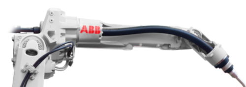
In this example we will look at the IRB 2600ID which has a hollow upper arm and wrist connected by a hose.
Click here to see the original rsxml for the IRB 2600ID/8-2.0
<?xml version="1.0"?>
<Mechanism xmlns="urn:abb-robotics-robotstudio-graphiccomponent" lengthUnit="mm" angleUnit="deg" name="IRB2600ID_8_200__03" modelName="IRB2600ID_8_200"
           type="Robot" kinematicsFlags="Articulated" motionControl="Kinematic">
  <Links baseLink="Base">
    <Part name="Base" source="IRB2600ID_8-200_BASE_CAD_rev02.SAT" />
    <GraphicComponentGroup name="Link1">
      <GraphicComponents>
        <Part name="Link1" source="IRB2600ID_8-200_LINK1_CAD_rev02.SAT"/>
        <Part name="Cables" source="IRB2600ID_8-200_CABLES_LINK1a_rev00.SAT"/>
        <Part name="Cables" source="IRB2600ID_8-200_CABLES_LINK1b_rev00.SAT"/>
      </GraphicComponents>
    </GraphicComponentGroup>
    <GraphicComponentGroup name="Link2">
      <GraphicComponents>
        <Part name="Link2" source="IRB2600ID_8-200_LINK2_CAD_rev02.SAT"/>
        <Part name="Cables" source="IRB2600ID_8-200_CABLES_LINK2_rev00.SAT"/>
      </GraphicComponents>
    </GraphicComponentGroup>
    <GraphicComponentGroup name="Link3">
      <GraphicComponents>
        <Part name="Link3" source="IRB2600ID_8-200_LINK3_CAD_rev02.SAT"/>
        <Part name="Cables" source="IRB2600ID_8-200_CABLES_LINK3_rev00.SAT"/>
      </GraphicComponents>
    </GraphicComponentGroup>
    <Part name="Link4" source="IRB2600ID_8-200_LINK4_CAD_rev02.SAT" />
    <Part name="Link5" source="IRB2600ID_8-200_LINK5_CAD_rev02.SAT" />
    <Part name="Link6" source="IRB2600ID_8-200_LINK6_CAD_rev02.SAT" />
  </Links>
  <Joints>
    <Joint name="J1" parent="Base" child="Link1" type="Rotational" active="true" point1="0, 0, 0" point2="0, 0, 1" />
    <Joint name="J2" parent="Link1" child="Link2" type="Rotational" active="true" point1="150, 0, 445" point2="150, 1, 445" />
    <Joint name="J3" parent="Link2" child="Link3" type="Rotational" active="true" point1="150, 0, 1345" point2="150, 1, 1345" />
    <Joint name="J4" parent="Link3" child="Link4" type="Rotational" active="true" point1="0, 0, 1495" point2="1, 0, 1495" />
    <Joint name="J5" parent="Link4" child="Link5" type="Rotational" active="true" point1="1088, 0, 1495" point2="1088, 1, 1495" />
    <Joint name="J6" parent="Link5" child="Link6" type="Rotational" active="true" point1="0, 0, 1495" point2="1, 0, 1495" />
  </Joints>
  <Limits>
    <Limit joint="J1" min="-180" max="180" />
    <Limit joint="J2" min="-95" max="155" />
    <Limit joint="J3" min="-180" max="75" />
    <Limit joint="J4" min="-175" max="175" />
    <Limit joint="J5" min="-120" max="120" />
    <Limit joint="J6" min="-400" max="400" />
  </Limits>
  <Flanges>
    <Flange name="wrist" link="Link6" x="0, 0, -1" y="0, 1, 0" z="1, 0, 0" t="1288, 0, 1495" />
  </Flanges>
  <HomePosition value="0, 0, 0, 0, 30, 0" />
  <JointMask value="1, 1, 1, 1, 1, 1" />
</Mechanism>
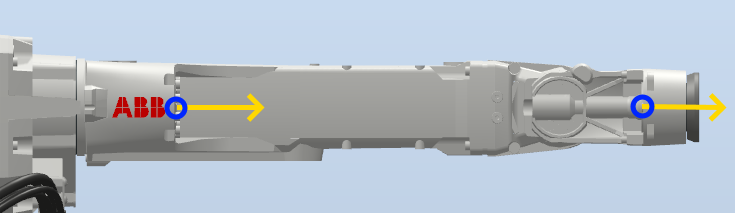
A cable is defined by adding a Cable element to the AdditionalComponents element in the rsxml. This element contains components that are not part of the kinematic chain of the mechanism.
The start and end points of the cable, and how it is connected to the kinematic parts of the robot, are defined by ControlPoint elements.
This is the xml for the hose connected to the upper arm (Link4) and wrist (Link5):
  <AdditionalComponents>
    <Cable radius="25" maxSegmentLength="50" name="Hose" color="32, 32, 32">
      <ControlPoints>
        <ControlPoint attachedTo="Link4" position="538.5, 0, 1495" direction="1, 0, 0"/>
        <ControlPoint attachedTo="Link5" position="1205, 0, 1495" direction="1, 0, 0"/>
      </ControlPoints>
    </Cable>
  </AdditionalComponents>
Cableadds a cable.radiusspecifies the radius of the cable.maxSegmentLengthspecifies the length of discretized linear segments in the physics simulation. A lower value increases fidelity but also CPU usage.colorspecifies the color of the cable in RGB.desiredLength(optional) defines the length of the cable if it should be longer than the total linear distance between the control points.youngsModulus(optional) defines the stiffness of the cable.
ControlPointdefines how the cable is attached and routed. There must be at least two control points.attachedTois the name of a component (typically a link) that the cable should be attached to at the point. If omitted, the point is only used for initial routing.positiondefines the position of the point, in global coordinates. The position should be defined so that the cable does not intersect other parts of the robot.directiondefines the direction of the cable at the point. If omitted the cable rotates freely.
Here are the control points (blue) and their direction (yellow) visualized on the original CAD geometry. Note that the direction must point "along" the cable in both places.
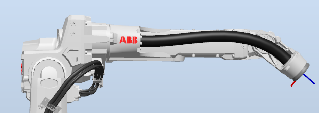
This is the final result:
Click here to see the complete rsxml for the IRB 2600ID/8-2.0
<?xml version="1.0"?>
<Mechanism xmlns="urn:abb-robotics-robotstudio-graphiccomponent" lengthUnit="mm" angleUnit="deg" name="IRB2600ID_8_200__03" modelName="IRB2600ID_8_200"
           type="Robot" kinematicsFlags="Articulated" motionControl="Kinematic">
  <Links baseLink="Base">
    <Part name="Base" source="IRB2600ID_8-200_BASE_CAD_rev02.SAT" />
    <GraphicComponentGroup name="Link1">
      <GraphicComponents>
        <Part name="Link1" source="IRB2600ID_8-200_LINK1_CAD_rev02.SAT"/>
        <Part name="Cables" source="IRB2600ID_8-200_CABLES_LINK1a_rev00.SAT"/>
        <Part name="Cables" source="IRB2600ID_8-200_CABLES_LINK1b_rev00.SAT"/>
      </GraphicComponents>
    </GraphicComponentGroup>
    <GraphicComponentGroup name="Link2">
      <GraphicComponents>
        <Part name="Link2" source="IRB2600ID_8-200_LINK2_CAD_rev02.SAT"/>
        <Part name="Cables" source="IRB2600ID_8-200_CABLES_LINK2_rev00.SAT"/>
      </GraphicComponents>
    </GraphicComponentGroup>
    <GraphicComponentGroup name="Link3">
      <GraphicComponents>
        <Part name="Link3" source="IRB2600ID_8-200_LINK3_CAD_rev02.SAT"/>
        <Part name="Cables" source="IRB2600ID_8-200_CABLES_LINK3_rev00.SAT"/>
      </GraphicComponents>
    </GraphicComponentGroup>
    <Part name="Link4" source="IRB2600ID_8-200_LINK4_CAD_rev02.SAT" />
    <Part name="Link5" source="IRB2600ID_8-200_LINK5_CAD_rev02.SAT" />
    <Part name="Link6" source="IRB2600ID_8-200_LINK6_CAD_rev02.SAT" />
  </Links>
  <AdditionalComponents>
    <Cable radius="25" maxSegmentLength="50" name="Hose" color="32, 32, 32">
      <ControlPoints>
        <ControlPoint attachedTo="Link4" position="538.5, 0, 1495" direction="1, 0, 0"/>
        <ControlPoint attachedTo="Link5" position="1205, 0, 1495" direction="1, 0, 0"/>
      </ControlPoints>
    </Cable>
  </AdditionalComponents>
  <Joints>
    <Joint name="J1" parent="Base" child="Link1" type="Rotational" active="true" point1="0, 0, 0" point2="0, 0, 1" />
    <Joint name="J2" parent="Link1" child="Link2" type="Rotational" active="true" point1="150, 0, 445" point2="150, 1, 445" />
    <Joint name="J3" parent="Link2" child="Link3" type="Rotational" active="true" point1="150, 0, 1345" point2="150, 1, 1345" />
    <Joint name="J4" parent="Link3" child="Link4" type="Rotational" active="true" point1="0, 0, 1495" point2="1, 0, 1495" />
    <Joint name="J5" parent="Link4" child="Link5" type="Rotational" active="true" point1="1088, 0, 1495" point2="1088, 1, 1495" />
    <Joint name="J6" parent="Link5" child="Link6" type="Rotational" active="true" point1="0, 0, 1495" point2="1, 0, 1495" />
  </Joints>
  <Limits>
    <Limit joint="J1" min="-180" max="180" />
    <Limit joint="J2" min="-95" max="155" />
    <Limit joint="J3" min="-180" max="75" />
    <Limit joint="J4" min="-175" max="175" />
    <Limit joint="J5" min="-120" max="120" />
    <Limit joint="J6" min="-400" max="400" />
  </Limits>
  <Flanges>
    <Flange name="wrist" link="Link6" x="0, 0, -1" y="0, 1, 0" z="1, 0, 0" t="1288, 0, 1495" />
  </Flanges>
  <HomePosition value="0, 0, 0, 0, 30, 0" />
  <JointMask value="1, 1, 1, 1, 1, 1" />
</Mechanism>
Note: The simulation of the cable is not initiated until the component is imported to a RobotStudio station. Therefore the cable is not visible in the preview image created by LibraryCompiler.exe.
Further considerations
Additional attributes
Key-value pairs known as attributes (not to be confused with XML attributes) can be added to the model data for customizing certain aspects of how the model is handled in RobotStudio, for example when creating a Virtual Controller from the station layout.
Attributes are defined by adding Attribute elements under an Attributes element:
<Mechanism name="IRB2600_20_165_C_01" modelName="IRB2600_20_165" type="Robot" kinematicsFlags="Articulated">
  <Attributes>
    <Attribute definition="true" key="AllowedTrackModels" value="IRBT4004 IRBT2005"/>
  </Attributes>
  <Links baseLink="Base">
  ...
An attribute can be added either to the instance or the definition of a model, this is controlled by the definition XML attribute.
This table shows the attributes that are recognized by RobotStudio:
| Attribute key | definition | Value and function |
|---|---|---|
AllowedTrackModels |
true |
Specifies one or more track models that can be used with a robot, for example "IRBT2005 IRBT4004". |
OverrideJointLimits |
true |
"true" for track models that use custom joint limits that must be pushed to CFG. |
WorkEnvelopeData |
true |
Contains data used to visualize the work envelope of a robot. The format is not yet public. |
Re-use CAD
A robot model with different variants often use common parts. It is recommended to use the same CAD and RSGFX files between variants to reduce redundant work. If the position of the parts differs between variants, they must be moved into the correct position in the .rsxml.
For example, here are the 0.9 m and 1.15 m variants of the IRB 1300. Links 3, 4, 5 and 6 (as well as the base) are identical and can be re-used:
 are identical")
If we use CAD parts with nominal positions that correspond to the smaller model, they must be moved 100 mm horizontally (x) and 150 mm vertically (z).
We do this by adding the t (translation) attribute to the links:
  <Links baseLink="Base">
    <Part name="Base" source="link0.SAT"/>
    <Part name="Link1" source="link1_1150-1400.SAT"/>
    <Part name="Link2" source="link2_1150-1400.SAT"/>
    <Part name="Link3" source="link3.SAT" t="100, 0, 150"/>
    <Part name="Link4" source="link4.SAT" t="100, 0, 150"/>
    <Part name="Link5" source="link5.SAT" t="100, 0, 150"/>
    <Part name="Link6" source="link6.SAT" t="100, 0, 150"/>
  </Links>